
FPGA Based Phasor Measurement Unit (PMU) for Smartgrid PART 2
In this part, Iam trying to explain how to measure the Voltage and current data using 8 bit ADC. First we need carefully read the datasheet of the ADC, there exist some configuration to using the device. Then we choose to use stand alone mode. The data input, should be connected into pin input to stepdown converter, since we set the rev voltage at 5V and GND (not -5 V) means at the stepdown converter we have to attach an offset voltage in order to get perfect sinusoidal voltage (since the ADC cant sampling minus voltage). after we set into standalone operation of ADC, then we need to connect the 8 output_pins itu FPGA. this ADC operates at 5V.
then how to read the data output from FPGA, shown at the FSM below:
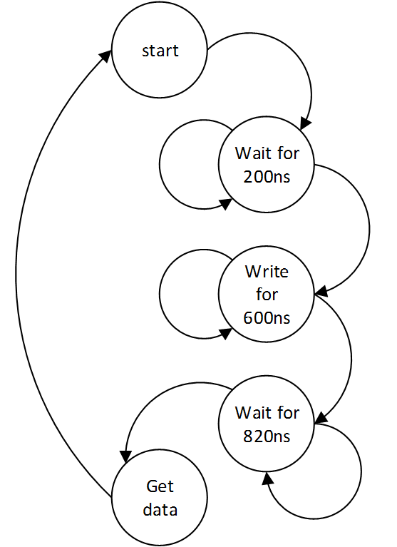
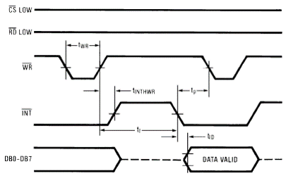
we can construct the FSM by reading the datasheet, ADC have several signals, they are CS, RD, WR, INT, and data out. in standalone mode CS and RD must be driven low, WR is the signal input, means we need to inject the WR with low signal about 600ns, then release it. by injecting the WR, the device will start the conversion. the conversion itself dauert 820 ns, then the data convertion will stay at the output buffer. we can collect the data after conversion. the standalone mode operation shown on figure bellow.
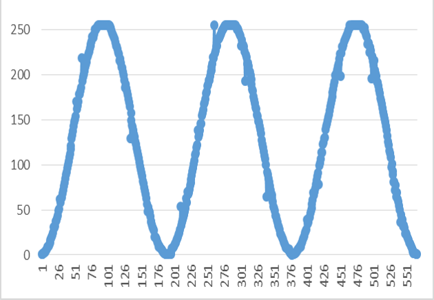
to collect the conversion data, we need to cast the data from ASCII Char to Unsigned INT. the results are shown figure bellow
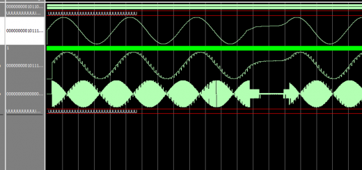
and the main block of ADC sampling iss shown bellow:


Recent Comments